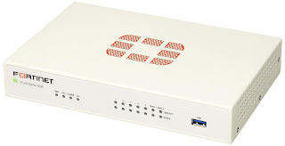
VLAN
VLAN is a group of devices on one or more LANs that are configured to communicate as if they were attached to the same wire, when in fact they are located on a number of different LAN segments. Because VLANs are based on logical instead of physical connections, they are extremely flexible.
It is a set of end stations and the switch ports that connect them. ... Like a bridge, a VLAN switch forwards traffic based on the Layer 2 header, which is fast. Like a router, it partitions the network into logical segments, which provides better administration, security, and management of multicast traffic.
VLANs support a logical grouping of network devices, they reduce broadcast traffic and allow more control in implementing security policies. Also, surveillance traffic is only available to those authorized, and bandwidth is always available, when needed.
You can create a VLAN using most switches simply by logging into the switch via Telnet and entering the parameters for the VLAN (name, domain and port assignments). After you have created the VLAN, any network segments connected to the assigned ports will become part of that VLAN.
VLAN is based on Layer 2 “Data link” of the OSI Model. The OSI layers are independent of each other and they communicate with each other. If any one of the layer gets compromised the other layers also fail. The VLAN is on the Data Link layer, which is as vulnerable to attacks as any other layer on the OSI model.
Trunk Port:
- Trunk ports are used to connect layer 2 devices together (when you need to expand your network)
IEEE 802.1Q frame tagging and native LAN in switch
The 802.1Q generally written as dot1Q is a data encapsulation method for VLAN tagging. Dot1q is Cisco proprietary and is also an open source protocol to use in VLANs. The length of VLAN tag is 4 bytes or 32 bits in length. Native LAN used for the data which have untagged Ethernet frames on trunk port. For Native VLAN both sides of the trunk line should have same configuration.
Configure and verify interswitch connectivity
Switch Configuration Scripts
Switch 1 Config.
switch>en
switch#conf t
switch#vlan 10
switch#name AD
switch#vlan 20
switch#name DE
switch#vlan 30
switch#name SR
switch#int fa0/1
switch#switchport mode access
switch#switchport access vlan 10
switch#int fa0/2
switch#switchport mode access
switch#switchport access vlan 20
switch#int fa0/3
switch#switchport mode access
switch#switchport access vlan 20
switch#int fa0/24
switch#switchport mode TRUNK
switch#switchport trunk allowed vlan 10,20,30
Switch 2 Config.
switch>en
switch#conf t
switch#vlan 10
switch#name AD
switch#vlan 20
switch#name DE
switch#vlan 30
switch#name SR
switch#int fa0/1
switch#switchport mode access
switch#switchport access vlan 10
switch#int fa0/2
switch#switchport mode access
switch#switchport access vlan 30
switch#int fa0/3
switch#switchport mode access
switch#switchport access vlan 30
switch#int fa0/24
switch#switchport mode TRUNK
switch#switchport trunk allowed vlan 10,20,30
Note
1.Vlan's are connected in same vlan only it will be communicate within a LAN network only.
2.It will reduce the network traffic.


Comments
Post a Comment
Thank You for your Response....